I was standing right here, in one of my favourite places in South Australia. This is Razorback Lookup in Ikara–Flinders Ranges.
Standing right there when my OM-1 jammed. I’d fired off one shot and as I went to wind the camera on, I got partway through the wind then everything stopped. It felt stuck-stuck, too. Nothing flexible about it at all. I took the film out and put the camera away. I’d forgotten to charge my SLR, too, so all I had to document this place was my mobile. It did a passable job, I guess.
I’d had a jammy idler-gear with this OM-1 previously, but this felt different. And my patented percussive method of jiggling the idler-gear into the right spot wasn’t working. I took the film out of the camera, and set it aside in a bag. I actually thought it might have been the end of it for the camera. Curtains for the shutter curtains, you could say.
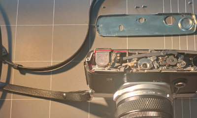
Feeling inspired today I began to pull the camera apart. I managed to get the camera un-jammed by jiggling the idler-gear. I was surprised.
The arrow shows the idler-gear, completely in the wrong position.
Here’s a video (with the lens off the camera…FOREBODING)showing the idler-gear in action.
I adjusted the little spring that keeps the idler-gear in the right spot, to make it a bit tighter. Tested the camera and it jammed again. I went through some basic trouble-shooting steps and it would sort itself out with the lens off. Fire perfectly with the lens off, and then not work again with the lens back on. The aperture lever felt fine – there was no way that it was causing enough resistance to jam the camera. Lens off: fine. Lens on: not fine.
Was it the lens? I put a different lens on and it worked perfectly. So it must be this 50mm f/1.8 lens causing problems somehow. The aperture levers felt the same on both lenses.
I played with the aperture ring. I played with the shutter speed ring. No better. Didn’t matter if it was set to 1/1000s or bulb. Then I changed the focus of the lens and when it wasn’t focused at infinity it was fine again. Tested it a few times. Back to infinity – no good. Away from infinity – good.
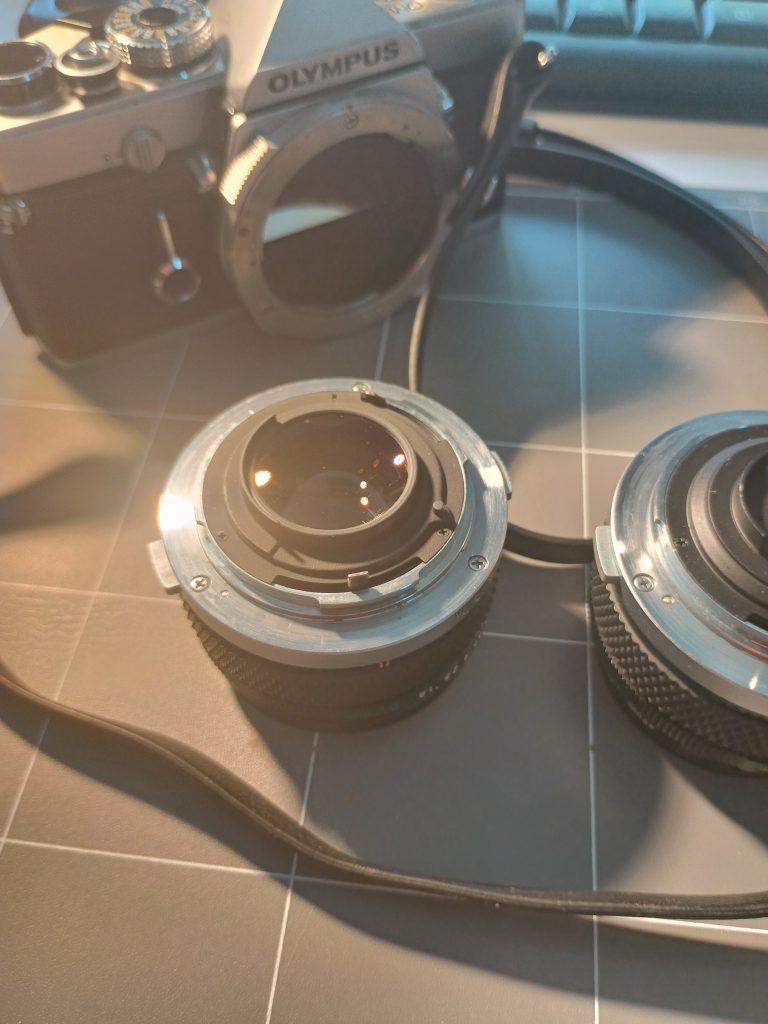
Turns out the rear element of the lens had come loose and was protruding a few millimetres further out than it should be and was getting hooked up on the mirror as it was trying to move out of the way. A quick tighten and we were back to normal.
The troublesome lens with the rear element no longer protruding out the back.
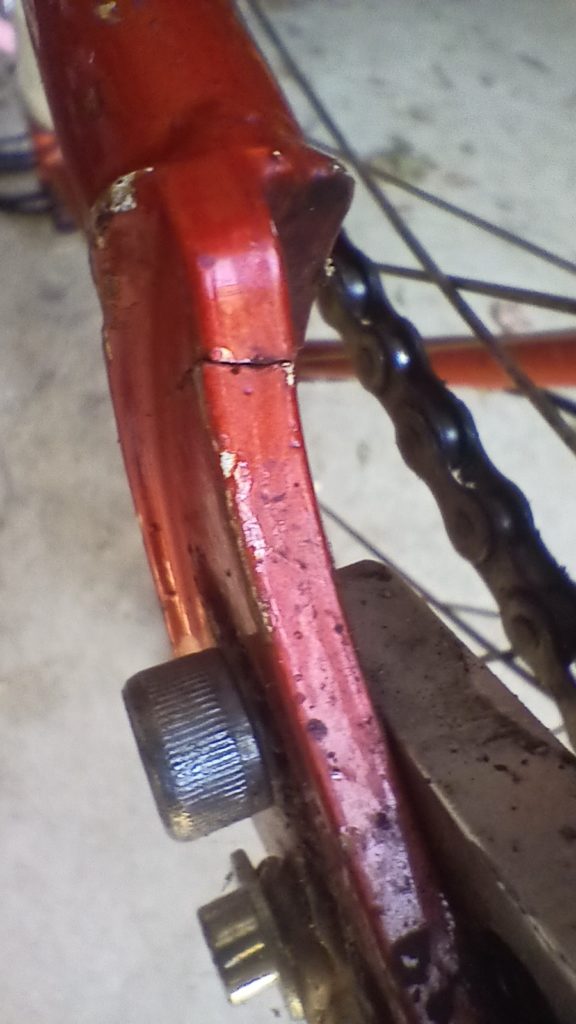
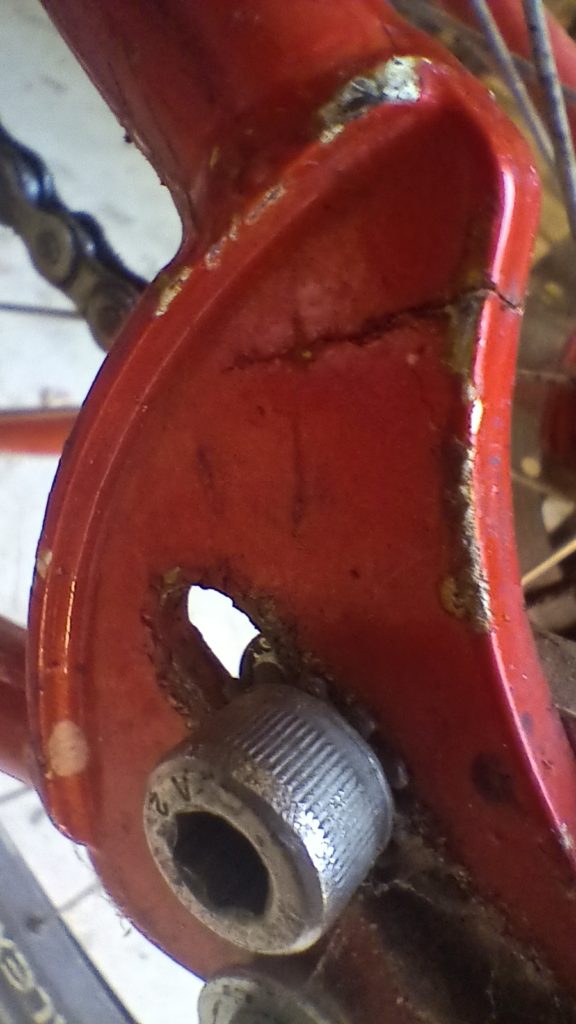
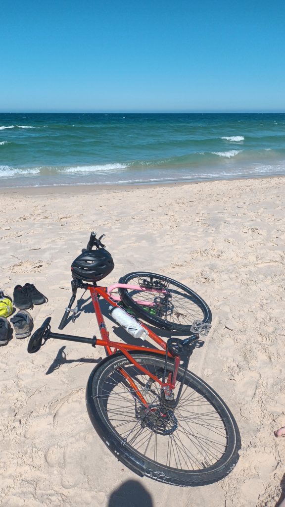
I was devastated when I realised that my Unit has a crack in the drive-side rear dropout. I was at the beach when it was spotted. I called half a dozen or so frame builders and welders, and so far only one has been willing to have a proper look at it, inside of 5-6 months, and even they aren’t ready to go for a few more weeks.
I didn’t realise how attached I was to this bike. We’ve had some amazing adventures, and I was planning many more.
Some photos of the broken bike below. I’m hoping I can get some photos of the repaired bike soon. And I need to figure out what colour to paint it.
I’ve reached D-1. Most people omit half of the answer to the question “how many bikes do I need?”, only saying that you need N+1 bikes, where N is the number of bikes you currently have. But the full answer is that you need N+1 bikes until N = D-1 where D is the number of bikes that will cause a divorce, or some other similar upheaval of your life. Anyway. I’m there. We don’t really have room for more bikes, and even though I buying a touring bike would be great, it’s not a good idea. I don’t need it.
I have a gorgeous 2008 Kona Unit 2-9. A rigid, single-speed mountain bike. I love it. I love the suppleness of the steel frame, and riding single-speed is good for the soul. Maybe. I figured that turning this bike into a tourer rather than the commuter I’ve got it set up to be at the moment would be a good way of not crossing into the dangerous N=D territory. It also won’t prevent the bike from being a commuter anyway.
This transformation will take place over a few stages. The first two stages have already happened. On-fork storage, and new handlebars with a few more hand-position options and carrying capacity.
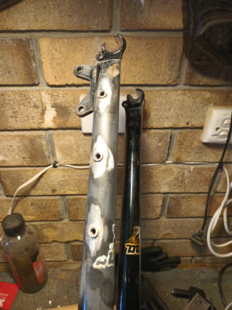
The 2-9 comes with a suspension corrected Project 2 fork. A lovely, simple fork with a straight 1-1/8″ steerer. Simple. Perfect, apart from not having any cage mounts. Local legend Peter Good – wielder of the oxy flame, conjurer of gorgeous brazed fillets – to the rescue. It wasn’t expensive. It didn’t take long. I got a pair of forks back that looked like this:
With some patience, sand paper, and rattle cans, I ended up with a pair of forks in gorgeous barbie pink.
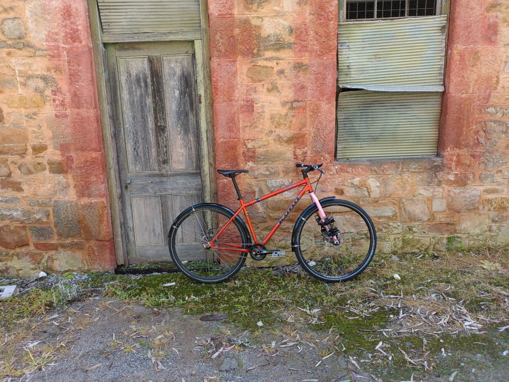
With racks mounted, it ended up looking like this:
Perfect.
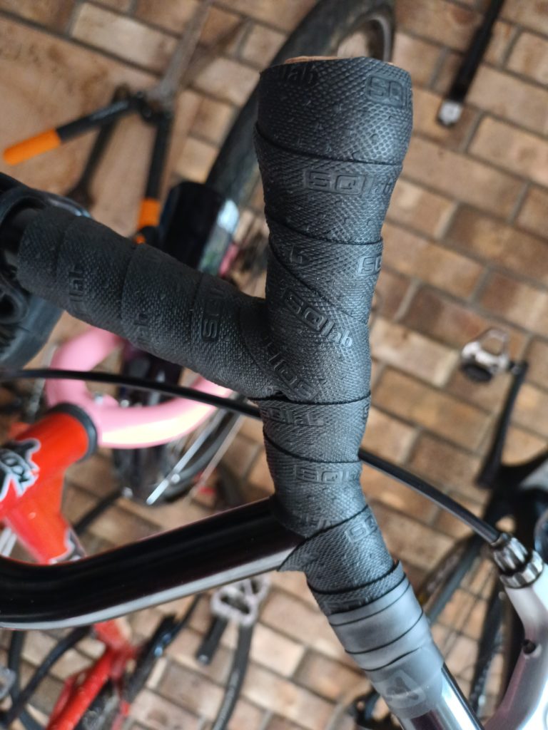
The next stage is new bars, and I settled on some Surly Moloko bars as being the right ones for me. Good sweep, and plenty of space. I did my first bar-tape job, and I’m pretty happy with how it all turned out.
The next step is a frame bag, and some sort of seat-post bag. Then I’m ready to go touring!
Leave me a comment if you have opinions on what else I should add to make this even better!
We’re all told to have strong passwords for everything. Long, good, complicated passwords with symbols, numbers, capital letters. Passwords that are a pain to enter without a passwords manager, in essence. Because password managers exist, that’s all good for nearly every situation, except when it comes to logging in to your desktop.
I know this kind of thing exists already, but I don’t think they exist quite as simply (and potentially as un-securely) as this.
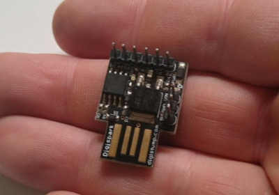
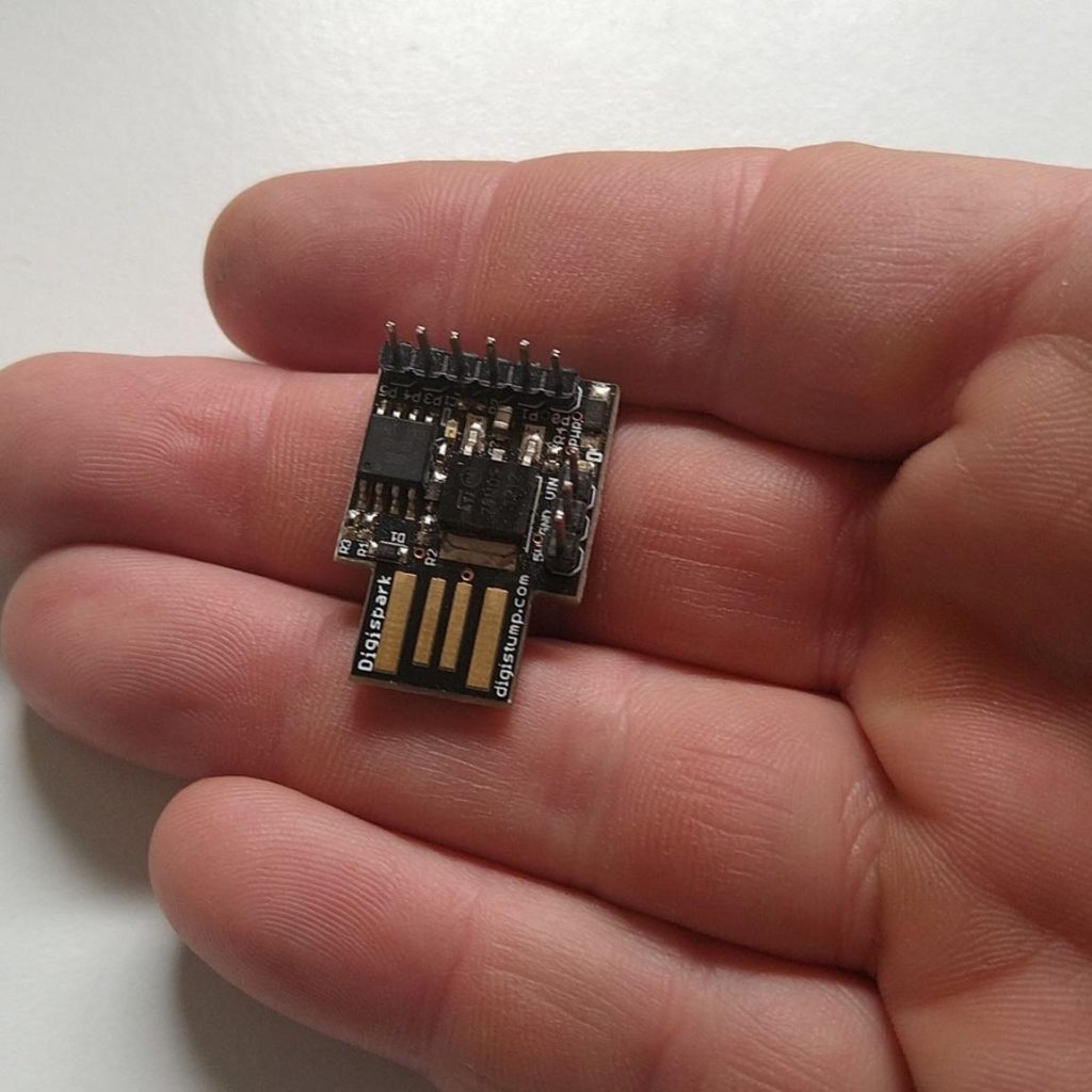
What I’ve made, using an old Digispark ATTiny85 arduino board with a built in USB-A plug, is a device that, when plugged in to a USB port, and the button is pressed, will type in a pre-determined string of characters followed by the enter key. There are two use-cases I can think of for this. Logging in to your desktop where there’s no password manager available, and entering your long-winded password into your password manager when setting that up.
There are obviously security issues with this – it’s a single factor authentication system. And you’re keeping the entire password available to anyone who picks up the doodad, plugs it in, and presses the button. There are things that could be done to make that safer – like only keeping part of the long-winded password on the device, requiring user input for to complete the password. But as a little one-hour project, this was fun.
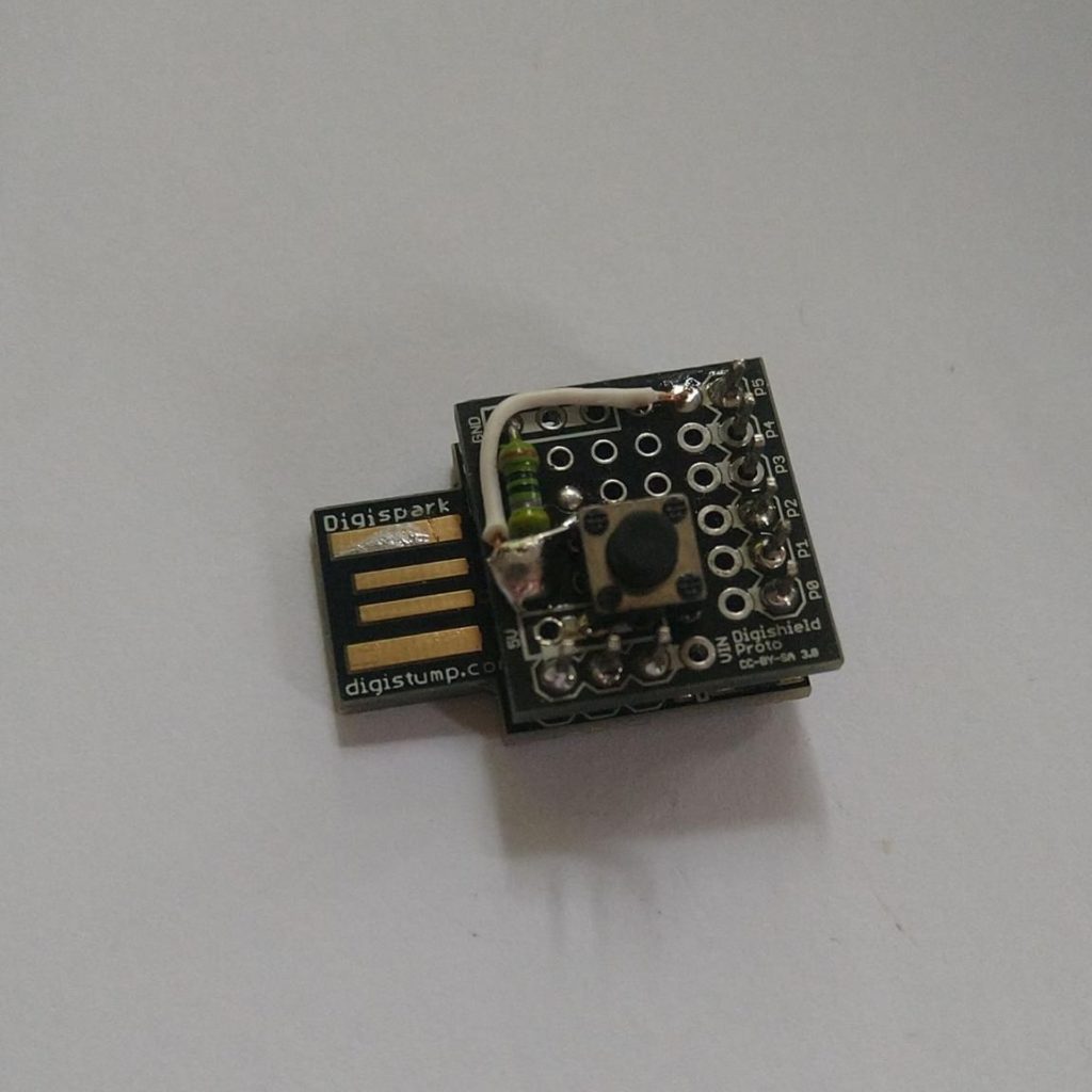
My soldering is a mess, but it works. The button circuit includes a pull-up resistor, to stop any erratic button behaviour when there isn’t a definite high or low signal, as per a tonne of tutorials online. Like this, straight from the Arduino source: https://www.arduino.cc/en/Tutorial/BuiltInExamples/Button
Here’s the completed product:
The code that’s running it is as below. Firstly, import the HID library from Digispark (there are tutorials on how to get that happening on the Digispark website). Initialise the button state, configure the required pin to wait for signal, then repeatedly wait for button press. If there’s a button press, send the defined string to the computer, and to prevent multiple entries, wait for a second before moving on.
I’ve been meaning to building a medium format scanner for a while now. I had a dodgily cobbled together one that was difficult to use, and because things didn’t quite line up, the backlighting was quite uneven. I woke up with the solution just the other day, went to my local hardware store to pick up the few things (60, I think) that I’d need. Here’s what I bought, enough to build a ~290 mm x ~290 mm scanner (which has a useable area, depending on your lens (I’ll get to that later), big enough for a 4″ x 5″ negative (but probably an 8″ x 10″, too):
1 x sheet of 600 mm x 1,200 mm 12 mm plywood 4 x 1,200 mm long M10 threaded rods 40 x M10 flanged nuts (or normal nuts and washers, doesn’t matter) Some wood-screws (I ended up needing 9 – just get a box) White plastic chopping board, at least 260 mm x 260 mm 2 x 5/16″ coarse threaded bolts (you’ll probably need to cut them to get the right length) A pane of glass (go to an op-shop and buy some old frames for a couple of bucks each) Wood glue
The tools I used:
Tablesaw Jigsaw Drill-press Drill Various drill-bits 90° square Angle-grinder (optional – I used it to fix an issue I created for myself) Measuring tape Spirit-level
Using the tablesaw, cut the plywood sheets into squares as big as you can/want/need. You need 3 at the very least, depending on a few things. I ended up using 5, but I will, down the track, replace one of them with a larger piece of chopping-board without a plywood frame.
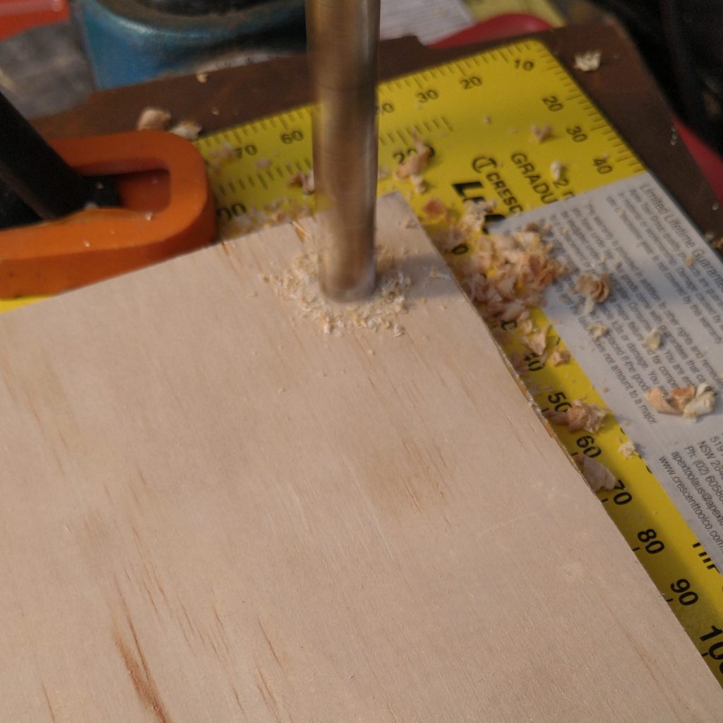
Drilling the corner holes
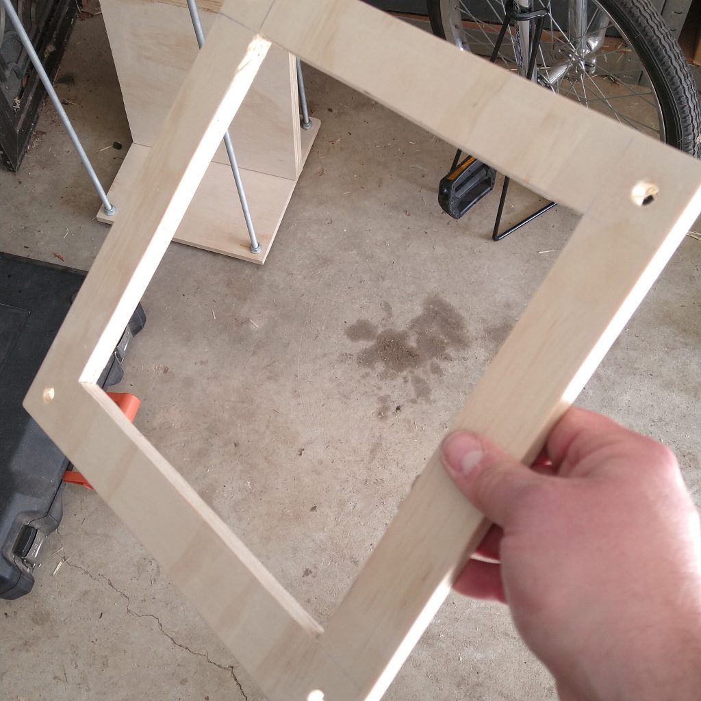
A square hole cut
Drill a 10mm hole in each corner of the squares. Exactly where you choose in the corner doesn’t matter too much, but make sure you’re consistent. I used a 90° angle clamped to my drill-press to act as a jig.
Measure roughly the distance between edge and centre of the drill-hole and double it and draw a square here, to cut out with the jigsaw. Drill corner holes and cut in a straight-ish line between them.
Measure the distance from the bottom of the remote flash-shoe to the centre of the flash head. Measure the distance from the centre of the lens on the camera to the bottom of the camera body. My flash was taller than half of the rectangle, so it had to be mounted on a 45° angle.
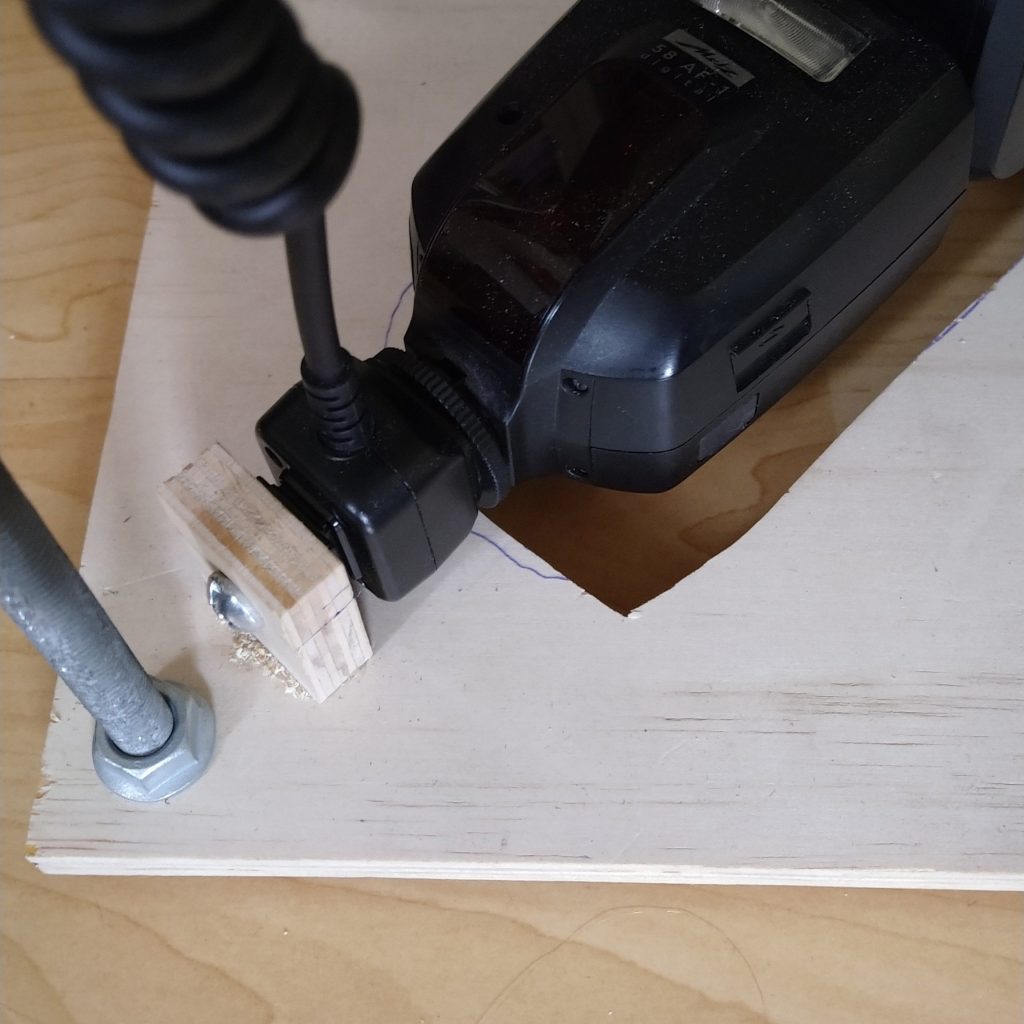
Place your flash in roughly the right spot on one of the square boards and trace around it with a pencil. Cut this section out, leaving a gap so you can get to the underside of the flash and pop the flash off to easily adjust settings and the like. Glue and screw a small piece of plywood the right distance from the centre of the board. Drill a 6mm hole in it, and mount the remote flash shoe here with a 5/16″ screw cut to the right length.
Flash Shoe in place
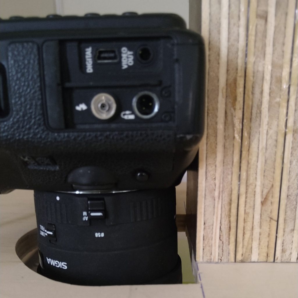
Camera in place
Mark the centre of another square board and mark the distance from the centre of the lens to underside of camera. Cut a hole large enough for the lens to easily fit through. With some off-cuts of ply glue and clamp a decent chunk of them together to give the camera a strong platform to be screwed to. Once the glue has dried, drill a hole in a suitable location and attach to board lining it up with the base-of-camera line. (I’ve just noticed my camera isn’t quite square…will have to fix that).
Cut a hole a bit smaller than the size of your chopping board/diffuser for the and screw the diffuser to it. My next step will to find a chopping board large enough to not need a wooden frame around it.
There’s going to be a lot of turning of nuts coming up. If you have a soft wheel you can attach to a drill, this will make life a lot easier. See my method here: https://www.instagram.com/p/CDXoiYVjuhv/
Now it’s just a matter of assembling the tower.
Drive the screws onto the threaded bar to the right level, and use a spirit-level (or measuring tape) to make sure each level is…er….level.
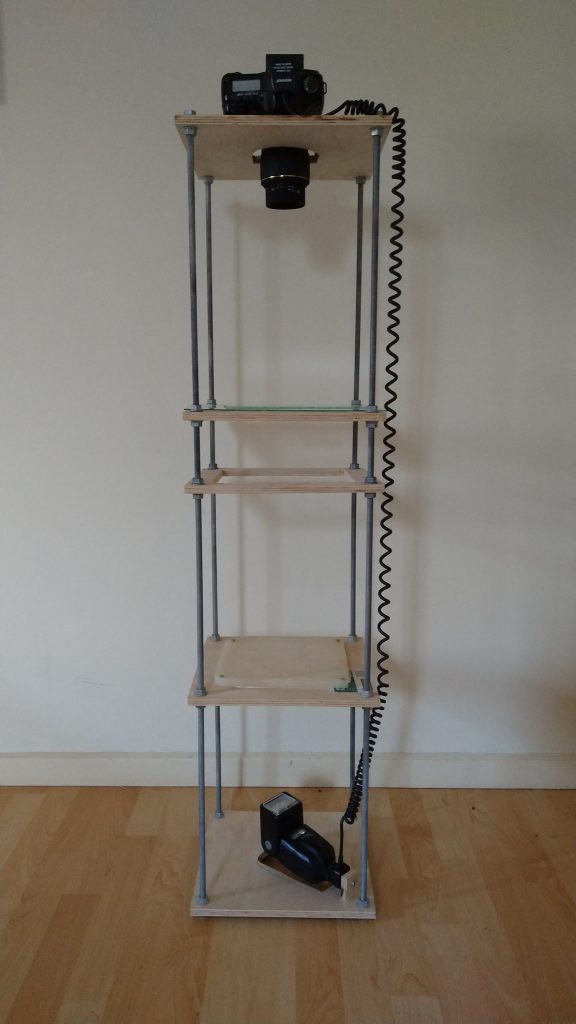
From the bottom up it goes:
Flash -> Diffuser -> Empty Square -> Second Empty Square (Optional – explanation below) -> Camera at the very top.
The reason you might want a second empty square, is if you’re doing a lot of 4″ x 5″ negatives, and a lot of 6 cm x 7 cm negatives, you can have them at the right distance from the camera to maximise how much of the negative there is in the frame.
You’re done! Clamp the negative between the sheets of glass and snap a photo. It will need cropping and inverting, but there are hundreds of ways of skinning that cat, so to the Google Machine for that.
I like new stuff. I think most people do. But I also adore old stuff. Stuff that maybe doesn’t work as well as it should, but has the potential to be great again.
Archaeological Find
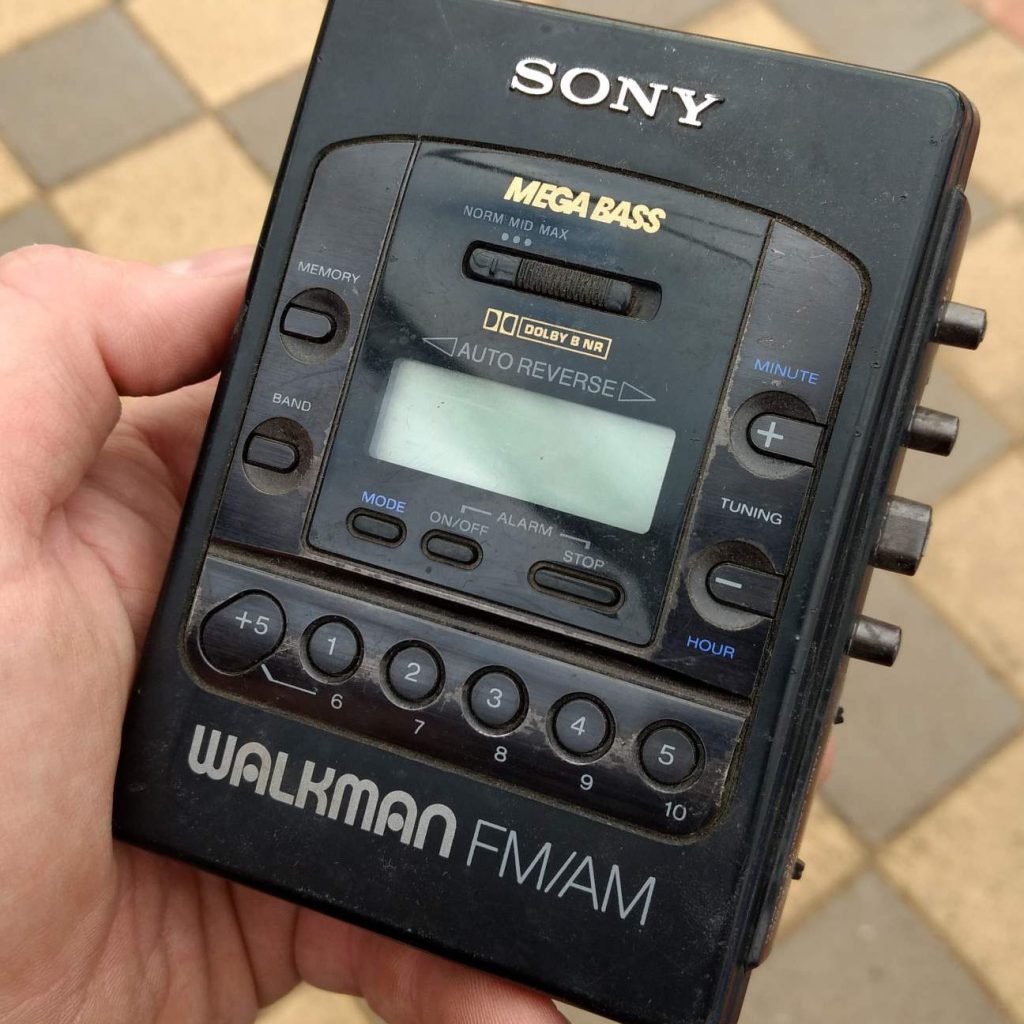
Our farm sold recently, which meant that the stuff I had stored there had to go…somewhere. Nearly everything went into a skip – I hadn’t seen it for 20+ years, and hadn’t missed it, so figured it was best to just dump everything without looking at it. Some boxes, though, triggered memories, and I figured it was a good idea to have a peek inside.
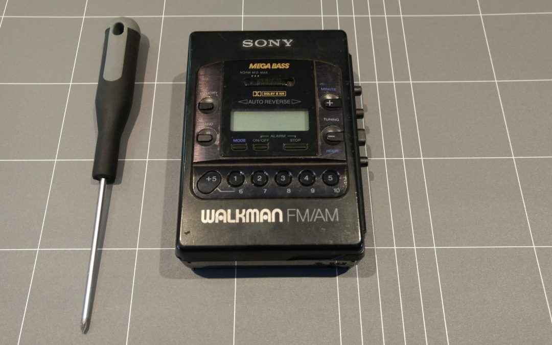
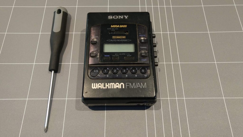
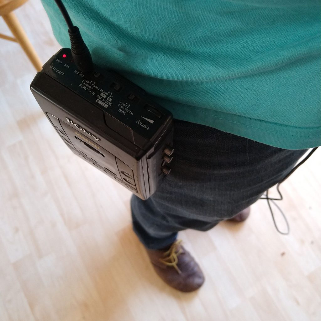
One of the things I found was my Walkman. It didn’t work. But it made most of the right noises, so I figured it couldn’t be too broken. Armed with a small #000 Phillips head driver, I opened it up to have a look. It was surprisingly easy to pull apart. Four screws, and the back came off without any plastic tabs to accidentally break off.
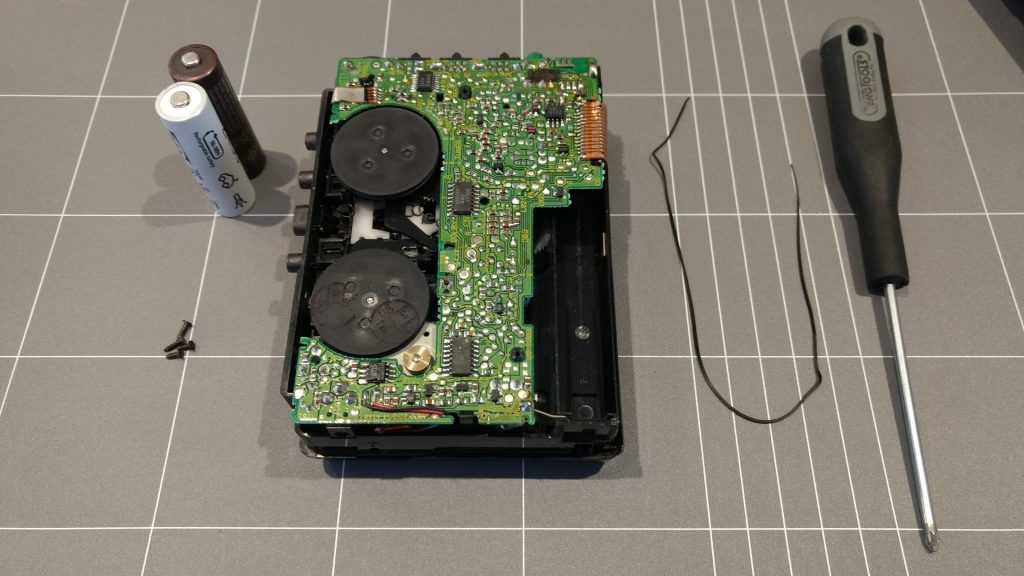
Inside was the drive-belt. Stretched and broken.
I had a look on ebay, and quickly found a supplier of new drive belts for the Walkman, and for under $10, one was on its way to me from Slovenia.
It arrived a couple of weeks later, and now I have a fully functional Walkman again.